Clearance & Compliance (M2)
The Clearance module checks whether the measured tunnel profile fully contains the design template – that is, whether the excavated section provides sufficient clearance for the intended use. Any point where the measured profile falls inside the template boundary represents an underbreak violation that may require remedial action.
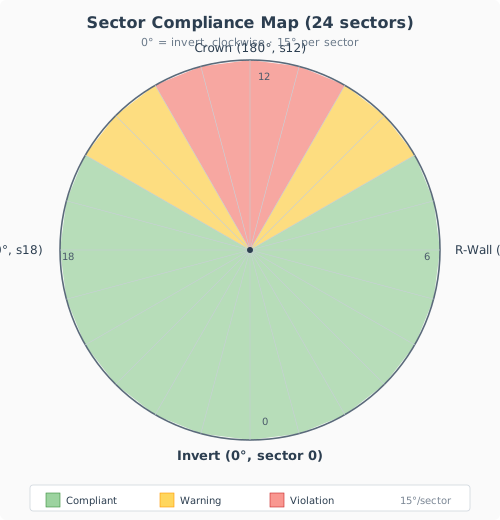
Cross-section divided into 24 angular sectors (15 degrees each). Green = compliant, yellow = warning, red = violation. Angle convention: 0° = invert (bottom), 90° = right wall, 180° = crown, 270° = left wall — measured clockwise.
How compliance checking works
The compliance check operates on the per-point deviation data produced by TTunnelDeviationEngine. Each measured point has a signed radial deviation: positive means the measured profile is outside the template (overbreak, compliant), and negative means it is inside the template (underbreak, violation).
The section perimeter is divided into angular sectors centered on the section axis. Each sector collects the deviation values of all measured points whose angle falls within the sector span. The sector’s status is determined by its minimum deviation value.
Sector assignment
Points are assigned to sectors based on their angular position, measured clockwise from the invert (bottom). With the default 24 sectors, each sector spans 15 degrees:
Sector 0: 0–15 degrees — invert (bottom)
Sector 6: 90–105 degrees — right wall
Sector 12: 180–195 degrees — crown (top)
Sector 18: 270–285 degrees — left wall
This matches the angle convention of TTunnelDeviationEngine.RadialAngle, which is the single source of truth for the whole Analytics suite.
Sector status classification
Each sector receives one of four status values:
Status |
Condition |
Meaning |
|---|---|---|
Compliant |
All points have deviation >= 0 |
Sufficient clearance in this sector |
Warning |
Minimum deviation between 0 and -threshold |
Marginal clearance – approaching violation |
Violation |
Any point has deviation < -threshold |
Underbreak detected – template not fully excavated |
No Data |
No measured points fall in this sector |
Insufficient survey coverage |
The warning threshold is configurable (default: 10 mm). Points with deviation between 0 and the negative threshold are in the warning band – technically compliant but close to the design boundary.
Note
Sectors with No Data status are treated as transparent for the purpose of violation arc detection. They do not break the contiguity of adjacent violation sectors, ensuring that a gap in survey coverage does not artificially split a single underbreak zone into two separate arcs.
Compliance results
The compliance check produces the following outputs:
Minimum clearance
The overall minimum clearance is the smallest radial deviation (in mm) across all measured points. A negative value means the closest point is inside the template – an underbreak violation. This single number summarizes the worst-case clearance condition for the section.
Sector map
A per-sector array of pass/warning/fail/no-data status values. This map can be visualized as a color ring around the section (green/yellow/red) to quickly identify problem areas. See Reporting (M6) for the polar diagram visualization.
Violation arcs
Contiguous groups of violation sectors are merged into violation arcs, each described by:
Start angle (degrees) – where the underbreak zone begins
End angle (degrees) – where the underbreak zone ends
Maximum depth (mm) – the worst underbreak within the arc
Violation arcs provide a concise description of where remedial excavation is needed.
Total violation arc
The sum of all violation arc spans, in degrees. This indicates how much of the section perimeter is affected by underbreak. A section with 360 degrees of violation arc has underbreak around the entire perimeter.
Overall pass/fail
The section receives an overall PASS if all sectors are compliant or warning, and FAIL if any sector has violation status.
When the Fail on warnings option is enabled in the configuration, warning sectors also cause an overall FAIL result. This stricter mode is useful for critical zones where any approach to the design boundary must be flagged.
Clearance threshold
The clearance threshold (configurable, default 0 mm) marks sections as critical in the clearance report when their minimum clearance falls below this value. This is separate from the per-sector warning threshold and operates on the overall section minimum.
Tip
Use the clearance threshold to flag sections that are technically compliant (no underbreak) but have very tight clearance. For example, setting the threshold to 20 mm will highlight any section where the measured profile comes within 20 mm of the template, even if it never crosses it.
Clearance heatmap — dashboard + PDF
A dashboard heatmap toggle exposes a Clearance mode alongside the Grade and Tolerance modes. The Clearance heatmap uses only two colours:
Red — the sector has
ssViolation(any measured point violates the template);Green — the sector is compliant;
Grey — no data in that bin.
Each heatmap bin’s midpoint angle is mapped into the corresponding compliance sector index (Trunc(MidAng / SectorAng)), so the 36-bin heatmap is a finer-resolution rendering of the same sector map described above.
The Clearance PDF report (see Reporting (M6)) includes the identical heatmap as a full page inserted between the chainage chart and the Clearance Details table. A reviewer can therefore use the heatmap to spot problem zones across the tunnel, then scroll to the per-section sketches where each red sector is drawn as a dashed red wedge on the polar plot. When the alignment looks toward decreasing chainage, both the heatmap and those sketches are mirrored, so a red band stays on the same side of the page as the wedge.
Violation sector wedges on section sketches
The per-section sketches in the Clearance PDF (and in the Grade and Tolerance PDFs — see Reporting (M6)) draw a dashed red wedge for every sector with ssViolation. Wedges are bounded by two radial dashed lines from the section centre to the outer radius and closed by a short red arc, forming a pie-slice that highlights the exact angular span of the underbreak. Adjacent violation sectors are merged: the shared radial boundary is skipped so that a continuous underbreak arc renders as a single wedge rather than a fence of radials.
Practical interpretation
All green sectors: The excavation fully contains the design profile with comfortable margin.
Yellow sectors at the crown: Common in drill-and-blast tunnels where the crown is difficult to control. Monitor on subsequent sections.
Red sectors at the walls: May indicate insufficient drilling depth or ground convergence. Check re-measurement data if available.
Large violation arcs: Suggest systematic under-excavation. Review drilling patterns and face advance procedures.
Warning
Underbreak is a safety-critical finding. Sections with Grade D (underbreak exceeding the configured maximum area) should be reviewed by the project engineer and may require re-excavation before lining installation.