Section Viewer
The Section Viewer is the primary tool for extracting measured cross-sections from point cloud data. It displays a 2D slice through the point cloud at each alignment station, applies configurable filters to isolate the tunnel surface, and samples the result into cross-section line data.
Open it via Point Cloud > Section Viewer.
Dialog layout
The Section Viewer window has four areas:
- Toolbar (top)
Toggle side panel | Prev/Next station buttons | Station number edit | Track bar slider | Plane mode | Slab thickness
- Side panel (left, collapsible)
Cloud list, station list, filter settings, extraction controls
- Section canvas (center)
2D rendering of the point cloud slice at the current station
- 3D preview (right)
Downsampled view of the checked point clouds, the alignment, and the section positions. Drag the splitter to give either pane more room.
Click the toggle button in the toolbar to collapse or expand the side panel, giving more room to the section canvas when needed.
3D preview
The right-hand pane shows the clouds that are checked in the side panel, thinned to a fixed preview budget so orbiting stays quick while you cut sections. Colours follow each cloud’s style (elevation, RGB, intensity, classification, or a single colour).
Cyan crosses — saved cross-section stations
Yellow plane — the station currently shown in the 2D canvas. The filled square is the cutting plane; the two faint rings sit half a slab thickness either side of it
White line — alignment centreline
Left-drag orbits, right-drag or middle-drag pans, the mouse wheel zooms, and a double-click fits the view. Checking or unchecking a cloud rebuilds the preview. Scrubbing the station moves the yellow plane without resampling the cloud.
Cutting plane
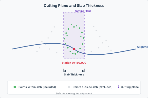
At each station, TunnelCAD constructs a cutting plane perpendicular to the alignment. All point cloud points within a certain distance of this plane are projected onto the 2D section view.
Plane mode
Two plane orientations are available:
- Vertical
The cutting plane is vertical – its normal lies in the horizontal plane along the alignment direction. The up direction is always world-Z. This is the standard mode for most tunnels.
- Perpendicular
The cutting plane is truly perpendicular to the alignment in 3D, accounting for the longitudinal gradient. The “up” direction tilts with the tunnel slope. Use this for steeply graded sections where a vertical cut would produce a skewed profile.
Slab thickness
The Slab Thickness parameter (in the toolbar) controls how thick the slice is around the cutting plane. Points within half the slab thickness on either side of the plane are included. A thicker slab captures more points but may introduce noise from adjacent geometry; a thinner slab gives a cleaner profile but may have gaps.
Tip
Start with a slab thickness of 0.5 m. Increase it if the section appears sparse (too few points), or decrease it if you see double-wall artifacts from adjacent rings or segments.
Cloud selection
The Cloud list (checkboxes at the top of the side panel) lets you choose which loaded point clouds contribute to the section slice. Uncheck a cloud to exclude it – useful when multiple scans overlap and you want to isolate one.
Filter settings
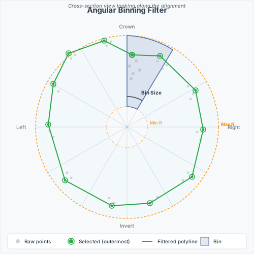
The filter transforms the raw point cloud slice into a clean polyline representing the tunnel surface. The algorithm divides the 2D section into angular bins radiating from the section center and selects one representative point per bin.
Filter mode
Four modes control which point is selected within each angular bin:
Mode |
Description |
|---|---|
Outermost |
Maximum radius – selects the point farthest from center. Best for detecting the excavation surface. |
Innermost |
Minimum radius – selects the point closest to center. Useful for finding the lining or shotcrete surface. |
Median |
Median radius – robust estimate that ignores outliers in both directions. |
Percentile |
User-defined percentile (0–100%). The Percentile spinner is enabled only when this mode is selected. |
Bin size
The angular width of each bin in degrees. Smaller bins produce a higher-resolution polyline but require denser point cloud data to fill each bin.
Default: 5 degrees (72 bins around the full circle)
Typical range: 1–15 degrees
Min / Max Radius
Distance range from the section center (in meters). Points outside this range are excluded before binning.
Min Radius: filters out points too close to the axis (e.g., survey targets, equipment near the center). Default: 0 m.
Max Radius: filters out distant outliers or points from adjacent structures. Default: 100 m.
Min Points Per Bin
The minimum number of raw points required in a bin to produce an output point. Bins with fewer points are skipped, leaving a gap in the polyline. This prevents isolated noise points from being treated as surface data.
Default: 3
Percentile
Active only in Percentile mode. Specifies which percentile of points (by radius) to select within each bin. For example, 90% selects the point at the 90th percentile of radius values – close to the outermost but ignoring the top 10% of outliers.
Proximity
A fraction (0–100%) controlling how many of the points closest to the cutting plane are kept before radius selection. At 100%, all points in the slab are used. At 50%, only the half closest to the cutting plane are kept per bin, reducing noise from the slab edges.
Gap threshold
When greater than zero (meters), the filter detects radial gaps within each bin. If the largest gap between consecutive points exceeds the threshold, only the outer cluster is kept. This removes ventilation ducts, cables, and other equipment that appear as inner rings in the section.
Template constraint
When a foreign object hangs inside the cross-section (a vent duct, hose, cable bundle, or similar), the angular-binning filter sometimes picks the object’s points instead of the wall behind it. The Template Constraint dropdown removes such points before they enter the per-bin selection.
The constraint compares each candidate point’s distance from the section centre against the template’s distance at the same angle. The template must be selected via the Template Line dropdown – pick a specific named line, not “All”, or the constraint silently disables and the hint label “select a single template line” appears below the controls.
Four modes:
Mode |
Behaviour |
|---|---|
None |
Constraint disabled (default – current behaviour). |
A. Reject inside |
Drops any candidate whose radius is more than |
B. Band (per-point) |
Keeps only candidates within |
C. Band (per-bin) |
Same band as B, but the template radius is sampled once at each angular bin’s centre angle and reused for every point in that bin. Slightly faster and easier to reason about when bin sizes are large. |
Inside Tol (m): how far inside the template a candidate may sit and still be kept. Default 0.10. Mode A uses only this value.
Outside Tol (m): how far outside the template a candidate may sit. Used only by modes B and C. Default 0.50, allowing typical excavation overbreak.
Where the template doesn’t define a wall along a given ray (e.g. an open template that doesn’t cover the invert), candidates along that ray pass through unconstrained – downstream rules (radius cap, gap, etc.) still apply.
Raw points removed by the constraint render as dim grey on the canvas, so you can see exactly which points were filtered and tune the tolerances accordingly. Points removed by other rules (elevation, MinR/MaxR, gap) keep their elevation-rainbow colour as before.
Tip
Start with mode A and Inside Tol = 0.10 m to sweep out objects in the tunnel interior without affecting the wall. If wall noise gets aggressive in mode A, try mode B with Outside Tol = 0.30–0.50 m to also cap stray outside-the-wall hits.
Elevation filters
Min Elevation
Excludes points below this elevation (relative to the section center, in meters). Set to a negative value to cut debris or water at the tunnel invert. Default: -999 (no cutoff).
Max Elevation
Excludes points above this elevation (relative to the section center, in meters). Useful for excluding overhead services or open-cut sections. Default: 999 (no cutoff).
Invert Skip Distance
Skips angular bins near the tunnel invert (bottom). The value is in degrees: it defines a symmetric zone around the bottom of the section (180 degrees from the top). Bins within this zone are excluded.
This is useful when the tunnel floor contains rail tracks, muck, or other material that does not represent the excavated surface.
0: no skip (default)
60: skips bins within +/- 30 degrees of the bottom
Canvas interaction
The section canvas shows the filtered polyline overlaid on the raw point cloud slice.
Action |
Effect |
|---|---|
Right-click drag |
Pan the view |
Middle-click drag |
Pan the view |
Scroll wheel |
Zoom in/out |
Home key |
Jump to first station |
End key |
Jump to last station |
Left/Right arrow |
Previous/next station |
Esc |
Cancel an in-progress drag and reset to the Move tool |
A coordinate grid is drawn in the background. The status bar at the bottom shows the total raw point count, the number of filtered (selected) points, the current chainage, and the empty/total bin ratio.
The hint label on the edit toolbar (see below) shows a live (Offset, Elev, dZ) cursor readout while the cursor is over the canvas.
Manual editing
The edit toolbar above the section canvas lets you correct the auto-sampled polyline by hand before committing it to the cross-section. Edits target the in-viewer working copy (the filtered preview); they do not touch the persisted cross-section until you click Sample Current.
Important
After editing, you must click Sample Current (or Sample Range) for the changes to take effect. Re-extracting (changing slab thickness, plane mode, slab, station, or any filter setting) discards uncommitted edits and rebuilds the preview from the cloud.
Edit tools
The toolbar groups three tool-radio buttons followed by two command buttons:
Tool / Command |
Effect |
|---|---|
Move (default) |
Click and drag a vertex (green dot) onto a different raw cloud point. |
Add |
Click on a raw cloud point to insert a new vertex. The new vertex is spliced into the polyline at the segment whose perpendicular distance to the click is smallest, so the line connects through it cleanly. |
Delete |
Click a vertex to remove it. A confirmation dialog appears the first time; Shift+click suppresses confirmations for the rest of the session. |
Reverse |
Reverses the polyline direction. Useful when the radial order needs to be flipped before sampling. |
Closed |
Toggle that controls whether the line is treated as closed. Drawn closed when on (with at least 3 vertices and no force-open filter active); written as |
Add and Move are snap-to-cloud: a small cyan square marker appears on the nearest raw point within ~12 px of the cursor. Clicking with no marker visible is a no-op. Move drags rubber-band visually but only commit to raw points; if no raw point is nearby on release, the vertex stays at its last snapped position.
Keyboard shortcuts
Key |
Effect |
|---|---|
Esc |
Cancel an in-progress drag (revert the vertex to its pre-drag position) and reset the active tool to Move. |
Del |
Delete the vertex currently under the cursor (subject to the same confirmation as the Delete tool). |
Edit lifecycle
Extract + filter at the target station (any combination of slab/plane/filter changes).
Pick a tool (Move/Add/Delete) and edit the preview. Toggle Reverse / Closed as needed.
Click Sample Current to commit the edited preview to the cross-section’s persisted line data.
Save the project to persist on disk.
The radial sort that Sample Current normally applies (clockwise from the invert) is suppressed when manual edits are present, so reversed direction and topologically-inserted points survive sampling. The user-driven Closed toggle takes precedence over the line definition’s default Closed flag at sampling time.
Tip
Re-extract is the explicit “discard edits” gesture. Any change to the slab, plane, filter, cloud check, or station triggers a fresh extract and filter, which clears the working preview and resets the toolbar to the Move tool.
Extracting sections
Line definition
Before extracting, select the target Line Definition from the dropdown. The extracted polyline is stored as line data under this definition in the cross-section. For example, select “Excavation” to store the scanned tunnel profile as the excavation line.
Template line
The Template Line dropdown controls which template overlay is displayed on the canvas for visual reference. Select “All” to see all template lines, or a specific one to focus on a single design profile.
Append mode
When Append is checked, the extracted points are merged with any existing line data at that station rather than replacing it. This is useful for combining data from multiple scans or from manual measurements.
Extract current station
Click Sample Current to extract the filtered polyline at the currently displayed station. The points are radially sorted (clockwise from the invert) and saved as line data in the cross-section.
Note
If the station does not yet have a cross-section, one is created automatically. The alignment geometry (insertion point, elevation, bearing, template) is computed from the alignment engine.
Extract a range of stations
Click Sample Range… to batch-extract sections within a chainage interval. A modal dialog opens with From station and To station edits, pre-filled with the tunnel start and end. A live label shows how many existing cross-sections fall in the chosen range (Sections in range: N / M).
Click Sample to confirm and run the loop. A confirmation dialog summarises the count and chainage range; on Yes, TunnelCAD iterates the in-range cross-sections, extracts and filters the point cloud slice at each one, and saves the result. A progress indicator is shown in the status bar.
Stations where the filter produces fewer than 2 points are skipped.
Tip
To re-sample every section (the previous “Sample All” workflow), open the dialog and click Sample without editing the chainage fields – the defaults already span the full tunnel.
Direction display
Check Show Direction to display the alignment direction arrow on the section canvas. This helps verify that the section orientation matches expectations (left/right sides of the tunnel).