Forepoling Umbrellas
A forepoling umbrella is a fan of pipes drilled ahead of the face from one collar chainage. TunnelCAD stores the design on the tunnel alignment and calculates stakeout coordinates from the template and the alignment. Each pipe is a straight line in project coordinates, from its collar to its tip.
One entry is one umbrella. To cover a drive with several overlapping fans, add one umbrella at each collar chainage. The list is ordered by collar chainage, lowest first. Two umbrellas at the same chainage keep the order they already had.
Opening the editor
Open Forepoling Umbrellas in either of these ways:
On the Alignment view, click Forepoling umbrellas on the alignment toolbar.
In the project tree, right-click the tunnel and choose Forepoling Umbrellas….
The command uses the tunnel selected in the tree, or the active tunnel when the selection is not a tunnel. The alignment needs horizontal geometry, and a template must cover the collar chainage.
The editor has the umbrella list on the left and the inputs across the top. Add creates an umbrella. Delete removes the selected one. Calculate fills the stakeout table. Export CSV writes that table. Export PDF writes the stakeout report. Draw axes puts the pipes on the alignment view. Close returns to the project. Edits are kept when the dialog closes.
What you enter
The .tun file stores these inputs. Collar and tip coordinates are calculated again whenever you calculate, draw, or open the sketch, so they follow the alignment if the geometry changes.
Angles in the form use the project angular unit (degrees, DMS, gradians, or radians). The file stores degrees.
Input |
Meaning |
|---|---|
Name |
Name of this umbrella. It becomes the alignment layer |
Collar chainage |
Station where every pipe of this umbrella starts. |
Template line |
Design line the collars are measured from, usually the excavation outline. The line must exist on the template that covers the collar chainage, and the arch window must lie on that outline. |
From crown |
Left-hand limit of the fan, in degrees from the crown. Negative is left. |
To crown |
Right-hand limit. Positive is right. From crown must be the left-hand limit, so it is smaller than To crown. |
Spacing |
Largest gap allowed between pipes, measured along the template line. |
Radial standoff |
Distance from the template line out to the pipe axis, away from the alignment axis. |
Pipe length |
Length of each pipe, measured along the pipe from collar to tip. |
Lookout |
Angle between the pipe and the alignment tangent, outward toward the collar. |
Diameter |
Pipe diameter written on the stakeout. It does not move the collar and it does not change the spacing. |
Decreasing station |
Drill the pipes back down the chainage. Leave it off to drill toward increasing chainage. |
A new umbrella starts from −60° to +60°, with spacing 0.40 m, radial standoff 0.15 m, length 12 m, lookout 6°, and diameter 0.114 m. Decreasing station is off. The collar chainage starts at the tunnel’s start chainage.
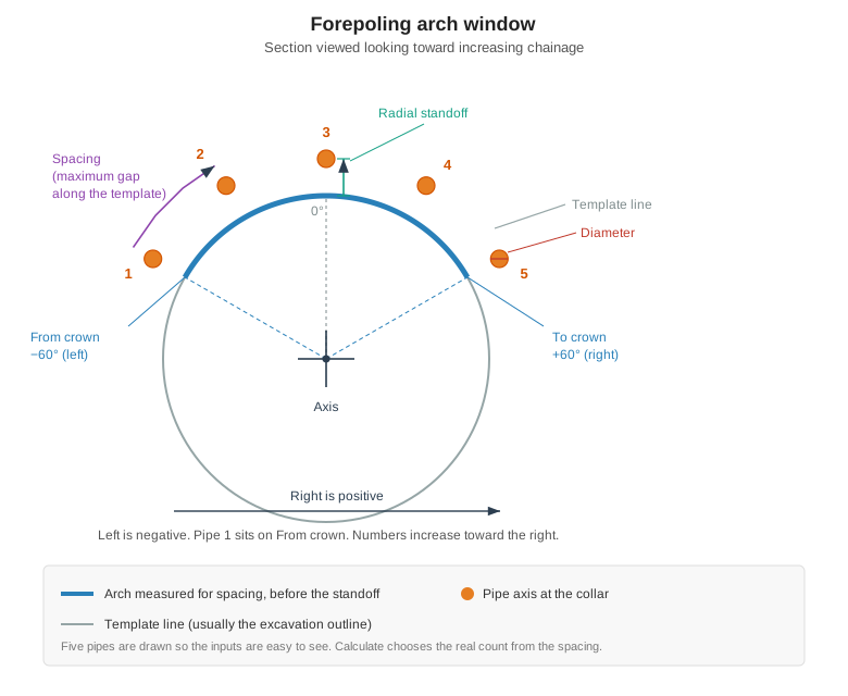
Arch window on the section. Left is negative and right is positive, looking toward increasing chainage. Spacing is measured on the template line. The radial standoff then moves each pipe axis outward.
Crown angles
Zero is the crown. The sign is the same as every other offset in TunnelCAD: looking toward increasing chainage, left is negative and right is positive. From crown is the left limit and To crown is the right limit.
Pipe 1 sits on From crown. The numbers increase toward the right, and the last pipe sits on To crown. Decreasing station does not swap left and right. The fan is still described looking toward increasing chainage.
Set From crown and To crown to the same angle to place a single pipe, for example 0 and 0 for one crown pipe.
Spacing
Spacing is the largest gap you will accept, measured along the template line before the radial standoff is applied. TunnelCAD measures that arch, then chooses the smallest number of equal gaps that stay at or under the spacing:
Gaps = the arch length divided by the spacing, rounded up.
Pipes = gaps + 1.
Actual spacing = arch length / gaps.
The end pipes stay on the two limits. The status line reports the pipe count and the arch length.
Example. A circular excavation of radius 5.00 m, from −60° to +60°, spacing 0.40 m. The arch is 120° of that circle:
120 / 360 × 2 × π × 5.00 = 10.472 m
10.472 / 0.40 = 26.18, which rounds up to 27 gaps, so 28 pipes. The actual spacing is 10.472 / 27 = 0.388 m. A radial standoff of 0.15 m puts the pipe axes on a radius of 5.15 m. That standoff is applied after the arch is measured, so it does not change the pipe count.
Radial standoff and diameter
The radial standoff is the distance from the template line to the axis of the pipe, measured away from the alignment axis in the section. The collar in the stakeout table is that point. The diameter is recorded beside it so the stakeout sheet can show the pipe size. The drawn axis is the centreline.
Lookout
Lookout is the angle between the pipe and the alignment tangent. The tangent includes the grade. Each pipe leaves that tangent in the plane that contains the tangent and the outward radial of its own collar.
At the crown the radial is upward, so the pipe rises above the alignment.
At a shoulder the same angle also carries the pipe outward, away from the axis.
The stakeout inclination is a different angle: it is the pipe above the horizontal. On a level tunnel, at the crown, the inclination equals the lookout. On a grade, or away from the crown, the two numbers differ. A climbing crown pipe has a larger inclination than its lookout, because the lookout is measured from the rising tangent and the inclination is measured from the horizontal.
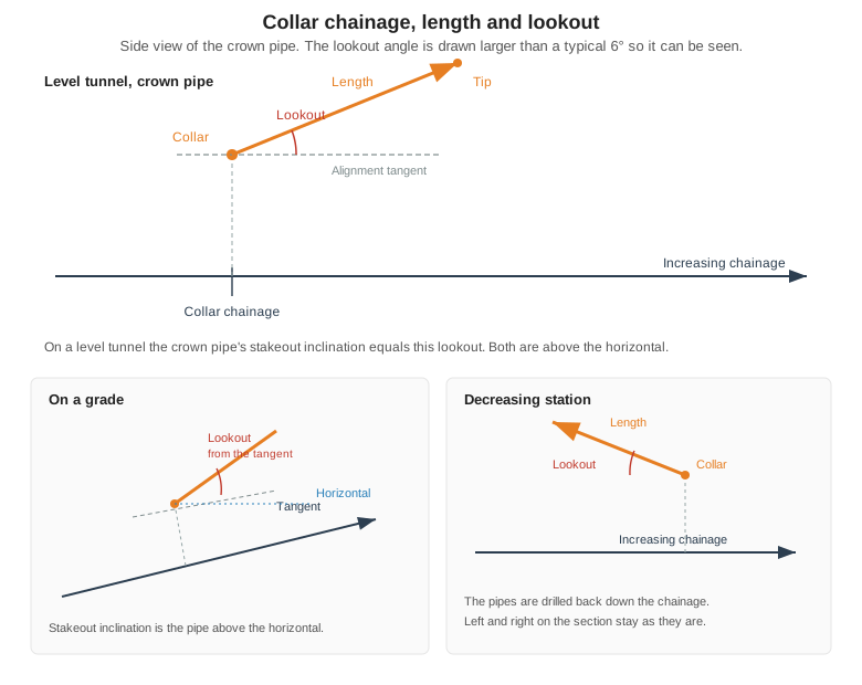
Collar chainage, pipe length, and lookout. Lookout is measured from the alignment tangent. The stakeout inclination is the same pipe measured from the horizontal. Decreasing station drills back down the chainage.
Decreasing station reverses the drilling direction. The pipes leave the collar toward decreasing chainage, and the lookout is measured from that reversed tangent. The section window is unchanged. On a level crown, a 6° lookout is still a 6° inclination, and the survey bearing turns by 180°.
Length is the distance from collar to tip along the pipe. The tip is not one length further along the chainage: on a curve, and whenever the pipe has a lookout, the chainage of the tip is shorter than collar chainage plus length.
Stakeout
Calculate checks the inputs and fills the Stakeout tab. The table has one row per pipe:
Column |
Meaning |
|---|---|
Pipe |
Pipe number. 1 is the left limit. |
Offset |
Collar offset from the alignment axis. Right is positive. |
Height |
Collar height above the alignment axis. |
Collar E, N, Z |
Collar easting, northing, and elevation. |
Tip E, N, Z |
Tip easting, northing, and elevation. |
Bearing |
Survey bearing of the pipe, clockwise from north, in the project angular unit. |
Inclination |
Angle of the pipe above the horizontal, in the project angular unit. |
Length |
Pipe length, in metres. |
Diameter |
Pipe diameter, in metres. |
Export CSV writes the same rows, plus the umbrella name and the collar chainage. Bearings and inclinations use the project angular unit, and the column title carries the unit (deg, gon, or rad).
PDF report
Export PDF writes a report in the same family as the Analytics reports. The cover is the TunnelCAD Analytics cover, the footer is the Analytics footer, and each later page uses the same title and subtitle. The default file name is <TunnelName>_Umbrella_<Name>.pdf.
The report has these pages:
Cover. Project, tunnel, and the chainage from the collar out to the tips along the alignment tangent. The count on the cover is the number of pipes. On a curve that chainage span is shorter than the pipe length, and it is not a chainage measured around the curve.
Design inputs. Every value from the dialog, in the project angular unit, plus the arch length, the number of gaps, the pipe count, and the actual spacing.
Collar section. The template line, the arch the spacing was measured on, and a circle at each pipe axis. Pipe 1 is the left limit. Left is negative, looking toward increasing chainage. Decreasing station does not swap the two sides.
Lookout. A side view at equal scale. The alignment tangent is drawn through the crown collar and includes the grade. Lookout is the angle off that tangent. A dashed line marks the horizontal when the tunnel is on a grade. The heavier line is the pipe nearest the crown. Decreasing station draws the pipes back down the chainage.
Stakeout. The same columns as the table, on a landscape page. Bearing is clockwise from north. Inclination is above the horizontal.
Chainages use the project station format. Coordinates use the project decimals.
The status line names the problem when a calculation cannot run. Typical causes are: the alignment has no horizontal geometry, no template covers the collar chainage, the chosen template line is missing or has no outline, the outline does not cover the whole arch window, From crown is to the right of To crown, or the spacing or the pipe length is not positive.
Sketch
The Sketch tab draws this umbrella in 3D, together with the alignment along the drilled length. A decreasing-station umbrella shows the alignment back down the chainage. Chainage labels sit on the alignment, and each pipe is numbered at its collar.
Drag to turn the view.
The wheel zooms.
The middle button pans.
Zoom extents fits the umbrella without changing the viewing angle.
A new calculation resets the view to a three-quarter view. Switching back to the Sketch tab keeps the view you had turned.
Draw axes
Draw axes switches to the Alignment view and draws one straight polyline per pipe, from collar to tip. The polylines go on a layer named Umbrella-<name>. Drawing the same umbrella again replaces that layer. The lines follow the current inputs, including Decreasing station.
Saved design
Each umbrella is stored inside its tunnel:
<Umbrellas>
  <Umbrella name="Umbrella 487" collarChainage="487.05"
            templateLine="Line B" fromCrownDeg="-60" toCrownDeg="60"
            spacing="0.4" radialOffset="0.15" length="12"
            lookoutDeg="6" diameter="0.114" decreasingStation="0" />
</Umbrellas>
fromCrownDeg, toCrownDeg, and lookoutDeg are degrees. decreasingStation is 1 when the pipes are drilled toward decreasing chainage, and 0 otherwise. A file written by an older build has no decreasingStation attribute; those umbrellas drill toward increasing chainage.
A realignment proposal copies these inputs onto the new alignment. Coordinates are not copied, because they are calculated from the alignment the umbrella belongs to.