Clipping Levels
Clipping levels restrict the area computation to a specific region of the cross-section. By enabling one or more clipping boundaries, you can isolate portions of the tunnel profile for targeted analysis – for example, computing area only below the invert level or only on one side of the tunnel axis.
How clipping works
When a clipping level is enabled, the polygon used for area computation is clipped to a rectangular boundary before evaluation. The clipping rectangle is defined by up to four independent boundaries:
Up – clips to a maximum Y (elevation) value. Area above this level is excluded.
Down – clips to a minimum Y (elevation) value. Area below this level is excluded.
Left – clips to a minimum X (offset) value. Area to the left of this offset is excluded.
Right – clips to a maximum X (offset) value. Area to the right of this offset is excluded.
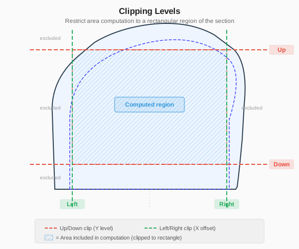
Clipping levels illustrated on a tunnel cross-section. Dashed lines show the Up, Down, Left, and Right clip boundaries. Only the area within the clipped region (shaded) is included in the computation.
Enabling clipping
Each clipping level is controlled independently in the Volume Definition Editor:
Check the checkbox next to the level (Up, Down, Left, or Right) to enable it.
Enter the clipping value in the adjacent text field.
Levels that are unchecked are ignored – no clipping is applied on that boundary.
You can enable any combination of the four levels. For example, enabling both Down and Right restricts computation to the lower-right quadrant of the section.
Coordinate system
Clipping values are specified in the section’s local coordinate system:
X axis – horizontal offset from the alignment axis. Positive values are to the right, negative values are to the left.
Y axis – elevation relative to the section’s reference point. Positive values are upward.
Important
The clipping values are in the same coordinate system as the section line data – local offsets, not world coordinates. A Down level of -2.0 means “exclude everything below Y = -2.0 in the section view.”
Use cases
Crown analysis
Enable the Up clipping level to restrict computation to the upper portion of the tunnel. Set the Up level to the springline elevation to analyze only the crown area.
Example: compute overbreak in the crown only, excluding the sidewalls and invert.
Invert analysis
Enable the Down clipping level to restrict computation to the lower portion. Set the Down level to the invert elevation to analyze only the invert concrete zone.
Example: compute the invert area for concrete volume estimation.
Side-specific analysis
Enable Left or Right clipping to analyze one side of the tunnel independently. This is useful when:
Different construction methods are used on each side
One side has a known geological condition requiring separate reporting
Comparing left vs. right excavation symmetry
Example: set Left to 0.0 to analyze only the right half of the tunnel (positive X offsets).
Combined clipping
Enable multiple levels simultaneously to define an arbitrary rectangular region. For example:
Down = -1.0 and Up = 3.0 – analyze only the zone between Y = -1.0 and Y = 3.0
Left = -5.0 and Right = 5.0 – limit analysis to a 10-meter-wide band centered on the axis
Additive constant
The Constant field in the Volume Definition Editor specifies a fixed value added to every section’s computed area result. This is applied after clipping and formula evaluation.
Use cases for the additive constant:
Systematic correction for known measurement bias
Accounting for a fixed material allowance per section
Adjusting for features not captured in the line data
Note
The additive constant is in the same units as the area result (m2 for area terms, meters for Length terms). It is added to the total formula result, not to individual terms.